:: STEPSTICKS mods, etc
 ** update **
adding a hunk of heat spreader to a stepstick. using a special high temp glue.
and with this heat spreader, an even larger heatsink can be now applied to the stick. somewhere in the region of 15mm x 15mm (instead of the normal 10mmx10mm)
 |
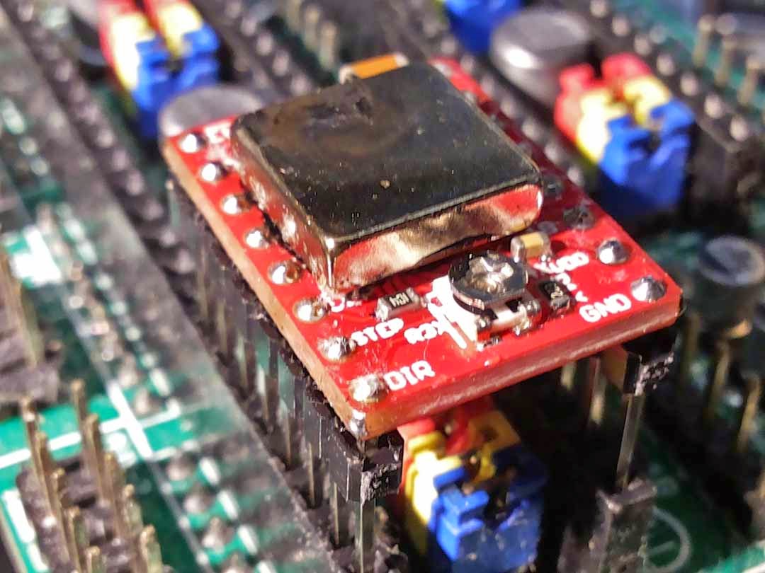
| add 2 additional caps @ power pins to reduce noise. |
 |
| bottom heat spreader mini block. extended 20mm pin-headers to enable addition of underbelly mods. |
 |
| perfboard side extension as finger grabs and addon space for more caps. |

if those little heat spreaders look familiar, its because they were magnets, de-clawed with high temperature treatment.

 |
| left big and right small. a definitely better way to channel off the heat (including the bottom spreaders) |
 |
| pure heat sink overkill. |
Its been many moons since i did anything to advance the building of my XYZ gantry system. which would complete my PCB milling machine.

i guess it is time to restart this.
and right back at square one, getting the stepsticks in the right drive.
as i have tinkered with them previously. i remembered certain made in china stepsticks come with a terrible un-usable ZERO ohm sense resistor (as you can see in the white stepstick)

the one on the left is from another supplier and comes with 0.2ohms

referencing from this article by "JOEM" on stepsticks (and references from allegro PDF) http://reprap.org/wiki/StepStick and http://www.allegromicro.com/en/Products/Motor-Driver-And-Interface-ICs/Bipolar-Stepper-Motor-Drivers/A4983.aspx. we can see that some suppliers use 30k for R5, some 20k. VREF max for 20k is 1.67v, for 30k is 1.25v. how ever due to high voltage noise spikes in driving steppers, i would think it is advisable to utilize higher voltages in feedback to improve signal to noise ratios.
based on 30k R5, the red stepstick max current limit is = VREF / ( 8 x Sense_resistor) = 1.04A. based on the 20k R5, if the same R15 is used instead of R00, the current limit would have been = 1.39A. with a R100 value, limit will be = 2.08A. with R200 value, limit will be 1.04A.
 BUT, strangely, this time with the help of better probes (http://3roomlab.blogspot.sg/2014/04/mini-show-and-tell-hirschmann-pms2600.html) i found that the component marked "30C" on the white stepstick is not 30k but also 20k. so ladies and gentlemen, "reprapdiscount" the seller, again avoid buying from them.
 based on a very well researched finding by nophead many moons ago on the off time required of R4 to achieve 1/16 microstepping http://hydraraptor.blogspot.sg/2012/04/stepstuck.html it is likely that i will also change the R4 to more than 47k to enable smoother 1/16 stepping.
the basis of the off time based on the equation in allegro PDF Toff approx = R4/825 (in microseconds). the standard 10k fit is for approx 12us. in nopheads reccomendation of R4=47k, Toff = 57us.
i think in the final mod i will use 180k (giving 218us). biggest challenge would be the tiny 0402 SMD sizes. at 218us, it is likely the stepper will become very audible at 4.6kHz), but that will not be much of a concern for me, as the number 1 concern is properly modding the stepstick to give proper drive to common stepper motors.

in my old post http://3roomlab.blogspot.sg/2013/03/rsenser4-experiments.html, i have already tried the 0R33 and 0R68 (0.63A and 0.31A limits). back then, i made the mistakes of wrong current limit calculations. and at that time, i have already tried R4 up to 440k (an odd ball trimmer value, it was marked as 500k, but measured was 440k).
so from here, to re-customize the stepsticks Rsense values to my 2 flavors of stepper motors. the NEMA17 sanyo will use 0.85A limit, 0.85 = 1.667 / (8 x R) ... R = 0R25. for my NEMA23 rated at 0.38A. R = 1.667/ (8 x 0.38) = 0R55. (based on extra headroom and IEEE SMD values, 0R22 and 0R47 will be selected. R4 will be selected as 180k). in addition to resistor mods, additional bypass capacitors will also be added.


Comments
Post a Comment
feel free to ask me anything