:: DIY heatsink thermal dissipation calculations
Update ::
New heatsink estimations. speed estimations of convective air current speeds taken from http://www.engineeringtoolbox.com/convective-air-flow-d_1006.html.
after trying the air speed convection effect to estimate capacity of sink. it is still faster to use ESP excel sheet. and this is a tabulation of some
| ˚C/watt | X | Y | fins | mm/fin | price | link (** fin height not compensated for base thickness) |
| 0.57 | 150 | 120 | 14 | 30 | $12.00 | http://shop110660058.taobao.com/?spm=2013.1.1000126.d21.6XXnO6 |
| 0.57 | 100 | 130 | 17 | 38 | $14.00 | http://item.taobao.com/item.htm?spm=a1z10.5-c.w4002-7041310241.56.pMzQnS&id=39042280706 |
| 3.97 | 45 | 45 | 10 | 18 | $1.50 | http://item.taobao.com/item.htm?spm=a1z10.5-c.w4002-6185675907.78.ZbUO8l&id=38133519414 |
| 4.19 | 37 | 37 | 9 | 24 | $1.45 | http://item.taobao.com/item.htm?spm=a1z10.5-c.w4002-6185675907.56.xt0HQs&id=38220590975 |
| 7.76 | 50 | 25 | 8 | 10 | $0.90 | http://item.taobao.com/item.htm?spm=a1z10.5-c.w4002-6185675907.70.QCmqkd&id=39528477964 |
| 8.21 | 30 | 30 | 5 | 25 | $1.30 | http://item.taobao.com/item.htm?spm=a1z10.5-c.w4002-6185675907.72.y7CVYE&id=39797440254 |
| 8.24 | 35 | 35 | 10 | 10 | $0.70 | http://item.taobao.com/item.htm?id=20651676362&spm=2014.12193480.0.0 |
| 9.51 | 35 | 35 | 4 | 17 | $1.40 | http://item.taobao.com/item.htm?spm=a1z10.5-c.w4002-7041310241.32.4AV8Av&id=38886831290 |
| 13.1 | 19 | 19 | 5 | 25.4 | $0.50 | http://item.taobao.com/item.htm?spm=a1z10.5-c.w4002-9065625388.33.HkSjgS&id=20187807225 |
| 14.3 | 28 | 19 | 8 | 13 | $0.55 | http://item.taobao.com/item.htm?spm=a1z10.5-c.w4002-9065625388.45.OWfUT3&id=19693945673 |
| 16.07 | 18 | 18 | 7 | 15 | $0.35 | http://item.taobao.com/item.htm?spm=a1z10.5-c.w4002-6185675907.29.EvswTK&id=42424643369 |
| 16.74 | 16 | 25 | 4 | 16 | $0.40 | http://item.taobao.com/item.htm?spm=a1z10.5-c.w4002-9065625388.84.5p2pDl&id=17026453150 |
| 16.85 | 23 | 23 | 6 | 12 | $0.53 | http://item.taobao.com/item.htm?spm=2013.1.w25148-8563864019.7.Yr0k0y&id=39618965425 |
| 18.05 | 20 | 20 | 5 | 16 | $0.55 | http://item.taobao.com/item.htm?spm=a1z10.5-c.w4002-9013026685.54.UtZgKL&id=37882097564 |
| 19.25 | 15 | 15 | 7 | 15 | $0.50 | http://item.taobao.com/item.htm?spm=a1z10.5-c.w4002-9065625388.21.HkSjgS&id=19189402178 |
| 19.8 | 16 | 21 | 5 | 25 | $2.00 | http://item.taobao.com/item.htm?id=40133389473&spm=2014.12193480.0.0 |
| 20.11 | 19 | 12 | 5 | 24 | $0.30 | http://item.taobao.com/item.htm?spm=a1z10.5-c.w4002-6185675907.33.EvswTK&id=38160776590 |
| 21.85 | 18.5 | 18.5 | 7 | 10 | $0.35 | http://item.taobao.com/item.htm?spm=a1z10.5-c.w4002-10025088838.27.QPVLxU&id=43673762789 |
| 27.34 | 16 | 16 | 4 | 16 | $0.25 | http://item.taobao.com/item.htm?spm=a1z10.5-c.w4002-6185675907.30.lTkB8u&id=38867957961 |
| 27.96 | 20 | 12 | 5 | 16 | $0.30 | http://item.taobao.com/item.htm?spm=a1z10.5-c.w4002-6185675907.36.tPuhtG&id=39450113337 |
| 29.12 | 20 | 20 | 7 | 6 | $0.20 | http://item.taobao.com/item.htm?spm=a1z10.5-c.w4002-6185675907.63.Cph20o&id=39324085689 |
| 29.76 | 15 | 9 | 7 | 15 | $0.20 | http://item.taobao.com/item.htm?spm=a1z10.5-c.w4002-9065625388.38.6RFeFf&id=21210423641 |
| 32.65 | 20 | 10 | 8 | 10 | $0.20 | http://item.taobao.com/item.htm?spm=a1z10.5-c.w4002-9065625388.57.HkSjgS&id=35834129450 |
| 33.1 | 19 | 13 | 4 | 11 | $0.50 | http://item.taobao.com/item.htm?spm=a1z10.5-c.w4002-9065625388.47.HkSjgS&id=18140014846 |
| 35.53 | 14 | 14 | 5 | 11 | $0.50 | http://item.taobao.com/item.htm?spm=a230r.1.14.112.cJG1k2&id=19637646588&ns=1&abbucket=8#detail |
| 37.85 | 13 | 13 | 4 | 14 | $0.20 | http://item.taobao.com/item.htm?spm=a1z10.5-c.w4002-9065625388.24.HkSjgS&id=22420952541 |
| 38.31 | 14 | 14 | 5 | 10 | $0.25 | http://item.taobao.com/item.htm?spm=a1z10.3-c.w4002-6185848390.31.mfqY98&id=38176746850 |
| 39.54 | 20 | 14 | 7 | 6 | $0.12 | http://item.taobao.com/item.htm?spm=a1z10.5-c.w4002-6185675907.24.Cph20o&id=39490312450 |
| 40.83 | 14.6 | 15 | 7 | 6 | $0.20 | http://item.taobao.com/item.htm?spm=a1z10.5-c.w4002-9065625388.30.993Iuk&id=21610063408 |
All these heatsink testing and experiments is going to be implemented on a test bed for LM2587
For a heatsink component 120mm x 69mm x 37mm, plugged into this website :

this calculation is based on this website : "http://www.engineersedge.com/calculators/heat_sink_convection_with_fins_calculator_10048.htm".
using heatsink.xls, we can estimate that the sink rating is about 0.76˚C/watt (emissivity = 0.9). with small fan, active sink now becomes approx 0.27˚C/watt (assuming heat flow rate is linear, peak heat transfer under ideal conditions could be up to 208watts? too high an estimate, me thinks. but the 0.27˚C/watt looks good.
for a virtual component with a T-junction at 100˚C, if the R-jc = 1˚C/w, R-cs = 1˚C/w and R-sa = 1˚C/w (assume ambient temperature = 10˚C, R-ja = 25˚C/w ). therefore total temperature difference = 90˚C, the main sink will pass [90˚C/(3R)] = 30watts, and a Ptotal of 33.6w (including R-ja = 3.6w)
with 30w going thru the main sink, to find the T-sink, we use T-sink = watt x R-sa. which gives us 30˚C. and that above T-amb, means the sink is @ 40˚C.
so thermally speaking, it is like ohms law. V = R x I, but unlike ohms law, knowing what the values are exactly can be a math nightmare. the actual numbers of a proper heat dissipation is no end of high level physics calculations with the endless variables of moving air particles which uses what i think is called fluid thermodynamics?
so thermally speaking, it is like ohms law. V = R x I, but unlike ohms law, knowing what the values are exactly can be a math nightmare. the actual numbers of a proper heat dissipation is no end of high level physics calculations with the endless variables of moving air particles which uses what i think is called fluid thermodynamics?
 this heat-sink pictured is 15cm x 12cm x 2.8cm. the 14 fins x15cm long are approx 2.5cm deep and it is ribbed surface. total approx surface area of fins = 980cm² (w/o numbers for ribs). approx surface area of base plate = 360cm². total = 1340cm². using the super simple approximation equation : 50/sqrt(area), we get a thermal coefficient of = 1.37˚C/watt.
there are also many other methods to calculate this value by searching for more data on the web, with some requesting at least USD9.90/mth to access some very "unique" data sets (NO WAY!!!). but thanks to some great people around the net, this XLS sheet is free --> sound.westhost.com/heatsink.xls . from this website http://sound.westhost.com/heatsinks.htm). using the XLS sheet and specifying for an upper temperature bla bla bla, we get 0.81˚C/watt (emissivity = 0.9), 0.92˚C/watt (emissivity = 0.7), 1.62˚C/watt (emissivity = 0.1 polished surface).
alternatively we can also use this calculator --> http://students.cs.byu.edu/~jgoodell/heatsink1.html. this site has a variable air speed input. from this, it is saying the above heatsink is 1.07˚C/watt. however, this version is complicated and somewhat confusing due to my lack of knowledge in fluid dynamics.
 moving on, looking at the effect of active air flow over heatsinks, without going into fuild dynamics and higher physics, we grab some whitepaper data from CRYDOM (http://www.crydom.com/en/Tech/Whitepapers/HS_WP_FA.pdf) and put these into a graph here
(to convert typical fan CFM numbers into LFM, use LFM = CFM / (area). shortcut to millimeter measured width based fans, LFM = CFM / (pi x [(mm/2) x 0.00328084]^2
typically, we can group types of fans into a general performance multiplier factor between 0.0 to 1.0. 40mms under 7CFM which translates into approx 300LFM, 60mms under 20CFM = 400LFM, 80-100mms under 40CFM = 420LFM, 120mms under 100CFM going at around 500LFM. by a simple glance, the effective improvements have a diminishing return as LPM goes higher. and we can never achieve a factor of 0.0 which is logical.
so assuming we stick a small 80mm fan to the sink to gain a factor of 0.35, we now get a thermal coefficient of 0.28˚C/watt using the same heatsink above by adding this fan. putting this back into the above virtual situation, we are now looking at (instantly almost a 3.5x increase in thermal dissipation for the sink) 39watts. the limitation is now the package R-jc.
if we replug all these factors into a real component, say SUD50P04-08 DPAK power PMOS. now with a max T-junction of 150˚C, if the R-jc = 1.7˚C/w, R-cs = 0.5˚C/w and R-sa = 0.28˚C/w (ambient temperature = 30˚C, R-ja = 50˚C/w ). total power envelop of this setup is 120/2.48 = 48watt.
but we do not really want to stress the component junction to the max. lets bring it down to say T-jmax = 120˚C,
so this setup
is 90/2.48 = 36watt.
 now lets say we use a smaller heatsink. this smaller unit is 116mm x 60mm x 22mm. 16fins x 20mm x 60mm x 1.5mm. using the XLS sheet, we get a thermal coefficient of 2.2˚C/watt (emissivity = 0.9), 2.5˚C/watt (emissivity = 0.7). this sink size is nearly perfect fit for 2x 60mm fans side by side. so if we plug in the multipliers for a generic fan at around 300LPM, we get approx (2.2 x 0.4) = 0.88˚C/watt. which is quite fantastic.
putting this smaller sink into the setup of our PMOS : T-junction
of 120˚C, R-jc = 1.7˚C/w, R-cs = 0.5˚C/w and R-sa = 0.88˚C/w
(ambient temperature = 30˚C, R-ja = 50˚C/w ). total power envelop of
this setup is 90/3.08 = 29.2watt. using this number, we try to find the T-sink, which is 0.88 x 29.2 = 25.7˚C. so we are expecting the heatsink to be approx 56˚C. using this temperature figure we can then also create an active temperature monitoring sub circuit which is very a useful temperature to know. otherwise, we can also add circuits to increase fan power. if that is being done, assuming we will increase the LPM to modify the multiplier factor by -0.1, that will result in a R-sa = 0.66˚C/, which results in 90/2.86 = 31.5watt. a very small 2 watt increase in envelop which is very disappointing (note that in order for a change of factor of -0.1 to happen, the LPM increase is almost 2x, for a 60mm fan, IT IS IMPOSSIBLE !!!)
if we happen to use a better R-cs interface of say = 0.1˚C/w. the above scenario becomes
90/2.68 = 33.6watt. still not much of an improvement because of the large limiting factor on R-jc = 1.7˚C/w.
90/2.68 = 33.6watt. still not much of an improvement because of the large limiting factor on R-jc = 1.7˚C/w.
in any case, with R-ja = 50˚C/w, we are looking at 90/50 = 1.8watt. just that case alone expending 1.8watts.

expanding this further, as we SMD-ize everything onto a PCB (example prototyping and squeezing everything onto a 5x5 seeed PCB). we also want to calculate and see the effect of thermal dissipation thru a 2 layer PCB with vias. again, we lift white paper data from a good source (http://www.ti.com/lit/an/snva419c/snva419c.pdf). in this TI article, we can find that a via 12mil diameter with 0.5oz thickness by itself performs at 261˚C/w. so the rational of many that more vias for the win is logical. by stitching 20 vias inside the thermal footprint of the subject component, we achieve 261/20 = 13˚C/w. by directly using the PCB as part of the thermal dissipation network, the thermal circuit becomes this
**insert update new pic

with the extra thermal resistance R-pcb in place, the equation now becomes : Tj = 120˚C, R-jc = 1.7˚C/w, R-cs = 0.1˚C/w R-pcb = 13˚C/w and R-sa = 0.28˚C/w (ambient temperature = 30˚C). total power envelop of this setup is 90/15.08 = 5.97watt. with a 40 via stitching : 261/40 = 6.5˚C/w, 90/8.58 = 10.5w.
if we use a smaller sink : Tj = 120˚C, R-jc = 1.7˚C/w, R-cs = 0.1˚C/w R-pcb = 13˚C/w and R-sa = 0.88˚C/w (ambient temperature = 30˚C). total power envelop of this setup is 90/15.68 = 5.74watt. with a 40 via stitching : 261/40 = 6.5˚C/w, 90/9.18 = 9.8w.
but the TI paper is somewhat, not very useful as i found below a better source of calculating the numbers for vias, which will relate directly to the actual PCB which can be made from SEEED.
by further googling, we find this site http:// circuitcalculator.com/ wordpress/2006/03/12/pcb-via-calculator/
this guy have it figured out in year 2006, and somewhat updated it in 2009 i think. and the year is now 2014. empowering hobbyists for over 8 years ! thanks brad ! at this point, we are solely focusing on via properties and its main thermal effects, we have not considered the package to pcb (non-via), we have also not considered case thru pcb(non-via), both of these will also contribute to the dissipation which i assume will be a couple of watts (just like R-ja, high ˚C/w numbers)
from brad's data, we can calculate the via for 0.6mm/23.7mil PCB 12mil hole, 0.5mil copper which yields 118˚C/w. and @ 1mm (39.4mils), we get a 197˚C/w. based on these 2 data, we get the following graph :
 with reference to SEEEDstudio PCB services (via/spacing limitations)
@ 0.6mm PCB thickness (re-adjusting for actual pad footprints). we have the following possibilities of via arrays :
with reference to SEEEDstudio PCB services (via/spacing limitations)
@ 0.6mm PCB thickness (re-adjusting for actual pad footprints). we have the following possibilities of via arrays :
13x : 118/13 = 9.08˚C/w (pad size 2.54x2.54mm / 100mils) = single ended landings
25x : 118/25 = 4.72˚C/w (pad size 5.1x5.1mm / 200mils) = SOT223
50x : 118/50 = 2.36˚C/w (pad size 10.2x5.1mm / 400x200mils) = SOT223
85x : 118/85 = 1.39˚C/w (pad size 8.9x8.9mm / 350mils) = DPAK
145x: 118/145 = 0.81˚C/w (pad size 11.4x11.4mm / 450mils)
204x: 118/204 = 0.58˚C/w (pad size 11.4x16.5mm) = TO220
and using the same website calculator, each 12milx0.5mil via has only a calculated ampacity of 1.14A, which is really low. if we tie this down with the possibility that the actual plating done by SEEED is even smaller, it will mean the above calculation will all need severe derating.
expanding this further, as we SMD-ize everything onto a PCB (example prototyping and squeezing everything onto a 5x5 seeed PCB). we also want to calculate and see the effect of thermal dissipation thru a 2 layer PCB with vias. again, we lift white paper data from a good source (http://www.ti.com/lit/an/snva419c/snva419c.pdf). in this TI article, we can find that a via 12mil diameter with 0.5oz thickness by itself performs at 261˚C/w. so the rational of many that more vias for the win is logical. by stitching 20 vias inside the thermal footprint of the subject component, we achieve 261/20 = 13˚C/w. by directly using the PCB as part of the thermal dissipation network, the thermal circuit becomes this
**insert update new pic
with the extra thermal resistance R-pcb in place, the equation now becomes : Tj = 120˚C, R-jc = 1.7˚C/w, R-cs = 0.1˚C/w R-pcb = 13˚C/w and R-sa = 0.28˚C/w (ambient temperature = 30˚C). total power envelop of this setup is 90/15.08 = 5.97watt. with a 40 via stitching : 261/40 = 6.5˚C/w, 90/8.58 = 10.5w.
if we use a smaller sink : Tj = 120˚C, R-jc = 1.7˚C/w, R-cs = 0.1˚C/w R-pcb = 13˚C/w and R-sa = 0.88˚C/w (ambient temperature = 30˚C). total power envelop of this setup is 90/15.68 = 5.74watt. with a 40 via stitching : 261/40 = 6.5˚C/w, 90/9.18 = 9.8w.
but the TI paper is somewhat, not very useful as i found below a better source of calculating the numbers for vias, which will relate directly to the actual PCB which can be made from SEEED.
by further googling, we find this site http:// circuitcalculator.com/ wordpress/2006/03/12/pcb-via-calculator/
this guy have it figured out in year 2006, and somewhat updated it in 2009 i think. and the year is now 2014. empowering hobbyists for over 8 years ! thanks brad ! at this point, we are solely focusing on via properties and its main thermal effects, we have not considered the package to pcb (non-via), we have also not considered case thru pcb(non-via), both of these will also contribute to the dissipation which i assume will be a couple of watts (just like R-ja, high ˚C/w numbers)
from brad's data, we can calculate the via for 0.6mm/23.7mil PCB 12mil hole, 0.5mil copper which yields 118˚C/w. and @ 1mm (39.4mils), we get a 197˚C/w. based on these 2 data, we get the following graph :
13x : 118/13 = 9.08˚C/w (pad size 2.54x2.54mm / 100mils) = single ended landings
25x : 118/25 = 4.72˚C/w (pad size 5.1x5.1mm / 200mils) = SOT223
50x : 118/50 = 2.36˚C/w (pad size 10.2x5.1mm / 400x200mils) = SOT223
85x : 118/85 = 1.39˚C/w (pad size 8.9x8.9mm / 350mils) = DPAK
145x: 118/145 = 0.81˚C/w (pad size 11.4x11.4mm / 450mils)
204x: 118/204 = 0.58˚C/w (pad size 11.4x16.5mm) = TO220
and using the same website calculator, each 12milx0.5mil via has only a calculated ampacity of 1.14A, which is really low. if we tie this down with the possibility that the actual plating done by SEEED is even smaller, it will mean the above calculation will all need severe derating.
in conclusion
1) avoid high R-jc above 1.5˚C/w. interestingly, most NXPs and IRFs seems to have better R-jc characters than other manufacturers in the DPAK range.
2) forget D2paks, the unpopularity makes these packages very expensive.
3) next best bet are LFpak/LFpak33 or power56 (mostly NXPs again)
the website also did a skin effect calculator
http://circuitcalculator.com/wordpress/2007/06/18/skin-effect-calculator/
1Mhz = 2.99mils
10Mhz = 0.95mils
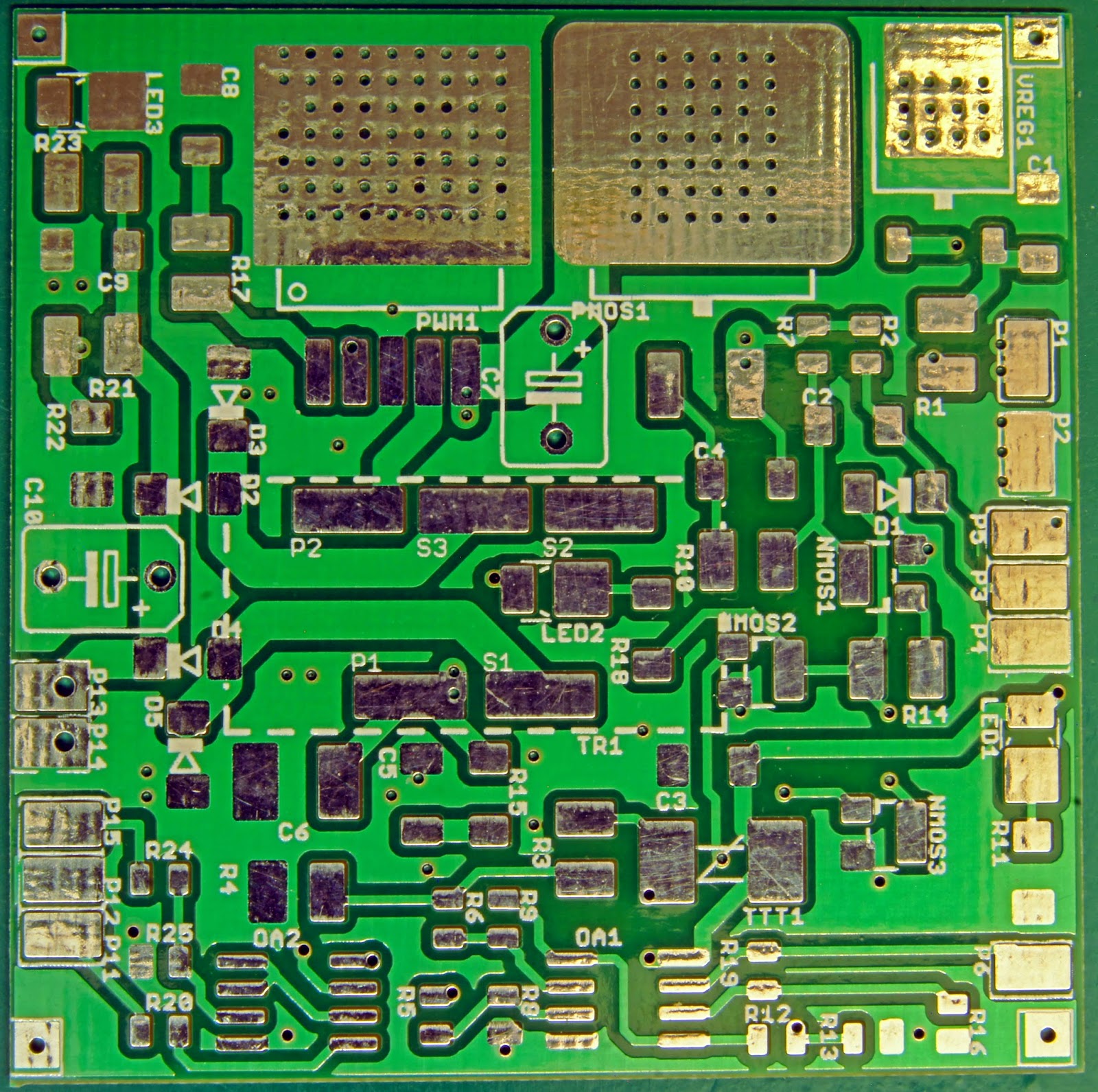
edit : POST reception of seeedstudio prototype 0.6mm PCB with 12mil vias (and generous tips from forum members in EEVblog)
there could be 2 additional variants of vias to try
 0.5mm (19.7mils) with 0.65mm (25.6mils) PCB. R-pcb 79.1˚C/w. ampacity 1.62A. dpak via population 70 vias (approx) which gives a final 1.13˚C/w (see pic on right)
for PMOS : Tj = 130˚C, R-ja = 50˚C/w, R-jc = 1.7˚C/w, R-cs = 0.1˚C/w R-pcb = 1.13˚C/w and R-sa = 0.88˚C/w (ambient temperature = 30˚C). total power envelop of this setup is 100/3.81 = 26.25watts. Rja additional 100/50 = 2 watts. gross total 28.25watts. T-pcb = 26.25 x (1.13+0.1+0.88) = 55.39˚C
for PNP : Tj = 130˚C, R-ja = 71.4˚C/w, R-jc = 6.25˚C/w, R-cs = 0.1˚C/w R-pcb = 1.13˚C/w and R-sa = 0.88˚C/w (ambient temperature = 30˚C). total power envelop of this setup is 100/8.36 = 11.96watts. Rja additional 100/71.4 = 1.4watts. gross total 13.36watts. the very high R-jc is a big problem. T-pcb = 11.96 x (1.13+0.1+0.88) = 25.24˚C
 (alternatively a larger 0.8mm (31.5mils) with 0.65mm (25.6mils) PCB. R-pcb 49.9˚C/w. ampacity 1.62A. dpak via population 35 vias which gives 1.51˚C/w)
SOT223 package, 27 via population, giving 2.93 ˚C/w.
taking numbers from LM317 TI pdf. R-ja 53˚C/w, R-jc 30.6˚C/w. assuming 25v loading @ 100mA = 2.5w. total thermal resistance = 30.6 + 2.93 + 0.1 + 0.88 = 34.51. T-jc @ 2.5w = 69.02˚C. which is a very nice level. Tsink = (2.93+0.1+0.88) x 2.5 = 9.78˚C
edit :: additional variations
assume thermal resistance of solder 0.0001˚C/w
assume thermal resistance of brass 0.00002˚C/w
assume brass to heatsink interface resistance 0.2˚C/w
assume total heatsink tab to heatsink total = 0.2˚C/w
with thermal brass tab interface, we are removing the PCB from the equation and directly "SMD" mounting to heatsink.
for PNP device we get Tj = 130˚C, R-ja = 71.4˚C/w, R-jc = 6.25˚C/w, R-brass = 0.2˚C/w and R-sa = 0.88˚C/w (ambient temperature = 30˚C). total power envelop of this setup is 100/7.33 = 13.64watts. Rja additional 100/71.4 = 1.4watts. gross total 15.04watts. the very high R-jc is a big problem. T-pcb = 13.64 x (0.2+0.88) = 14.73˚C
for PMOS : Tj = 130˚C, R-ja = 50˚C/w, R-jc = 1.7˚C/w, R-brass = 0.2˚C/w and R-sa = 0.88˚C/w (ambient temperature = 30˚C). total power envelop of this setup is 100/2.78 = 35.97watts. Rja additional 100/50 = 2 watts. gross total 37.97watts. T-brass = 35.97 x (0.2+0.88) = 38.85˚C
http://circuitcalculator.com/wordpress/2007/06/18/skin-effect-calculator/
1Mhz = 2.99mils
10Mhz = 0.95mils
interesting !!!
edit : POST reception of seeedstudio prototype 0.6mm PCB with 12mil vias (and generous tips from forum members in EEVblog)
there could be 2 additional variants of vias to try
0.5mm (19.7mils) with 0.65mm (25.6mils) PCB. R-pcb 79.1˚C/w. ampacity 1.62A. dpak via population 70 vias (approx) which gives a final 1.13˚C/w (see pic on right)for PMOS : Tj = 130˚C, R-ja = 50˚C/w, R-jc = 1.7˚C/w, R-cs = 0.1˚C/w R-pcb = 1.13˚C/w and R-sa = 0.88˚C/w (ambient temperature = 30˚C). total power envelop of this setup is 100/3.81 = 26.25watts. Rja additional 100/50 = 2 watts. gross total 28.25watts. T-pcb = 26.25 x (1.13+0.1+0.88) = 55.39˚C
for PNP : Tj = 130˚C, R-ja = 71.4˚C/w, R-jc = 6.25˚C/w, R-cs = 0.1˚C/w R-pcb = 1.13˚C/w and R-sa = 0.88˚C/w (ambient temperature = 30˚C). total power envelop of this setup is 100/8.36 = 11.96watts. Rja additional 100/71.4 = 1.4watts. gross total 13.36watts. the very high R-jc is a big problem. T-pcb = 11.96 x (1.13+0.1+0.88) = 25.24˚C
(alternatively a larger 0.8mm (31.5mils) with 0.65mm (25.6mils) PCB. R-pcb 49.9˚C/w. ampacity 1.62A. dpak via population 35 vias which gives 1.51˚C/w)SOT223 package, 27 via population, giving 2.93 ˚C/w.
taking numbers from LM317 TI pdf. R-ja 53˚C/w, R-jc 30.6˚C/w. assuming 25v loading @ 100mA = 2.5w. total thermal resistance = 30.6 + 2.93 + 0.1 + 0.88 = 34.51. T-jc @ 2.5w = 69.02˚C. which is a very nice level. Tsink = (2.93+0.1+0.88) x 2.5 = 9.78˚C
edit :: additional variations
assume thermal resistance of solder 0.0001˚C/w
assume thermal resistance of brass 0.00002˚C/w
assume brass to heatsink interface resistance 0.2˚C/w
assume total heatsink tab to heatsink total = 0.2˚C/w
with thermal brass tab interface, we are removing the PCB from the equation and directly "SMD" mounting to heatsink.
for PNP device we get Tj = 130˚C, R-ja = 71.4˚C/w, R-jc = 6.25˚C/w, R-brass = 0.2˚C/w and R-sa = 0.88˚C/w (ambient temperature = 30˚C). total power envelop of this setup is 100/7.33 = 13.64watts. Rja additional 100/71.4 = 1.4watts. gross total 15.04watts. the very high R-jc is a big problem. T-pcb = 13.64 x (0.2+0.88) = 14.73˚C
for PMOS : Tj = 130˚C, R-ja = 50˚C/w, R-jc = 1.7˚C/w, R-brass = 0.2˚C/w and R-sa = 0.88˚C/w (ambient temperature = 30˚C). total power envelop of this setup is 100/2.78 = 35.97watts. Rja additional 100/50 = 2 watts. gross total 37.97watts. T-brass = 35.97 x (0.2+0.88) = 38.85˚C


Comments
Post a Comment
feel free to ask me anything